







Aspheric Lenses in Aberration Theory
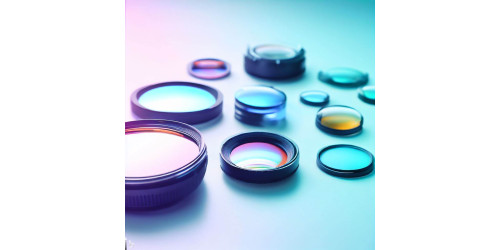
In classical optical design, a single positive spherical lens cannot eliminate spherical aberration merely by adjusting its bending factor. Marginal rays focus closer to the lens than paraxial rays, forcing traditional systems to rely on complex multi-element combinations that increase weight, length, and tolerance accumulation. The introduction of aspheric surfaces fundamentally overcomes this restriction, allowing optical architectures to approach the diffraction limit with far fewer optical elements.
This article is the first installment of the IADIY Optomechanical JDM Technical Series: Large-Aperture Aspheric Optics Trilogy, focusing on the geometric formulation of aspheric surfaces, Seidel aberration limits, and aperture stop placement trade-offs.
Quick answer: Can an aspheric surface eliminate all optical aberrations? No. Under third-order Seidel aberration theory, placing an aspheric profile at the aperture stop () corrects spherical aberration independently without altering off-axis aberrations. Away from the stop, however, its effects on coma, astigmatism, and distortion are strongly coupled through ray height ratios (). Furthermore, an asphere cannot correct Petzval field curvature or primary chromatic aberration. Its core value lies in unlocking geometric degrees of freedom, reducing overall lens count by 30% to 50%.
【IADIY Large-Aperture Aspheric Optics Trilogy】Navigation
- Part 1 (This Article): Aspheric Lenses in Aberration Theory: Seidel Correction Limits & Stop Positioning
- Part 2: 【Thermal Optics】Optical Glass vs. Plastic: dn/dT, Thermal Focal Drift & Moldable Glass Practice
- Part 3: 【Process Limits】Precision Glass Molding (PGM) Tolerance Limits: IADIY Ø80mm Volume Production
1. Where Does Spherical Aberration Come From? Physical Limitations
A spherical optical surface has only one geometric degree of freedom: vertex curvature. While this curvature defines the focal length in the paraxial region, the outer marginal zones are constrained by the exact same radius. Consequently, marginal rays experience excessive refraction relative to paraxial rays and focus closer to the lens surface, creating spherical aberration.
Spherical aberration is an on-axis monochromatic aberration that degrades image contrast and high-frequency modulation transfer function (MTF) across the entire field. Its magnitude scales steeply with numerical aperture (NA). For a single positive spherical element, shape bending can only minimize spherical aberration, never eliminate it. Conventional systems must combine positive and negative elements to cancel out aberrations, significantly increasing physical envelope, mass, and alignment sensitivity.
2. Mathematical Formulation of Aspheric Surfaces & ISO 10110-12
Aspheric designs break free from the constant-radius constraint by superimposing an even-order polynomial onto a standard conic section base to define surface sag across radial distance :
- : Vertex curvature (, reciprocal of vertex radius).
- : Conic constant:
- : Standard Sphere
- : Prolate Spheroid
- : Paraboloid
- : Hyperboloid
- : Oblate Spheroid
- : Higher-order polynomial deformation coefficients.
By keeping the vertex curvature constant, first-order paraxial properties (effective focal length and back focal length) remain stable. The higher-order terms selectively alter marginal ray trajectories, suppressing high-order aberrations.
Engineering Note: Traditional even-order polynomial coefficients exhibit strong cross-correlation, which can cause edge-sag oscillations during optimization. Optical design programs (Zemax, Code V) also normalize radii differently. Forbes orthogonal polynomials (Q-bfs / Q-con) represent deviations normal to a best-fit sphere, making mold core diamond turning and profilometer metrology far more stable. Optical production drawings must strictly comply with ISO 10110-12.
3. What Can Aspheric Surfaces Correct—and What Can't They?
In third-order Seidel aberration theory, an asphere's corrective leverage depends on its position relative to the aperture stop (expressed as the ratio of chief ray height to marginal ray height ):
| Aberration Type | Aspheric Correction | Physical Mechanism & Limitations |
| Spherical Aberration | Fully Correctable | Located at the stop (), the asphere alters spherical aberration exclusively without inducing off-axis aberrations. |
| Coma, Astigmatism, Distortion | Conditionally Correctable | Away from the stop, these aberrations change in tandem with . A single asphere cannot independently balance all three; multi-asphere configurations are required. |
| Petzval Field Curvature | Uncorrectable | Petzval sum depends strictly on optical power and refractive index. An asphere can only introduce astigmatism to flatten tangential or sagittal fields artificially. |
| Primary Chromatic Aberration | Uncorrectable | Chromatic aberration stems from material dispersion. It must be balanced using optical doublets or glass pairings with divergent Abbe numbers (). |
The true value of an aspheric element lies in unlocking geometric freedom: achieving identical or superior optical resolution while cutting total lens count by 30% to 50% and shrinking the mechanical tolerance stack-up.
4. Single Aspheric Elements & Diffraction-Limited Criteria
According to Fermat's Principle, when collimated light in glass refracts into air, designing the exit surface as a hyperboloid with conic constant eliminates on-axis spherical aberration completely at the design wavelength, reaching the diffraction limit.
In metrology and component acceptance, compliance with the diffraction limit is governed by established wave-optics thresholds:
- Maréchal Criterion: Wavefront RMS error (corresponding to a Strehl Ratio ).
- Rayleigh Criterion: Wavefront peak-to-valley error .
Next in This Technical Series
Once geometric optimization is complete, how do materials perform across automotive temperature extremes (-40°C to +85°C)? Should you select moldable glass or optical plastic? Continue to Part 2:
【Thermal Optics】Optical Glass vs. Plastic: dn/dT, Thermal Focal Drift & Moldable Glass Practice
5. Frequently Asked Questions (FAQ)
Can a single aspheric lens replace all spherical lenses in a system?
No. Aspheric surfaces eliminate monochromatic aberrations like spherical aberration and coma, but cannot resolve material dispersion (chromatic aberration) or alter intrinsic Petzval field curvature. Color-corrected imaging systems still require complementary glass types with balanced Abbe numbers.
Why is placing an asphere at the aperture stop most effective for spherical aberration?
At the aperture stop, the chief ray height is zero (ȳ = 0). The aspheric sag profile selectively modifies marginal ray heights without altering off-axis ray paths, decoupling spherical aberration correction from field-dependent coma and astigmatism.
What is the engineering advantage of Forbes Q-polynomials over standard even-order aspheres?
Traditional even-order polynomials suffer from high mathematical correlation, where tiny coefficient changes cause edge-sag oscillations. Forbes Q-bfs polynomials are orthogonal, directly mapping departure from a best-fit sphere to improve toolpath stability in single-point diamond turning (SPDT) and interferometric convergence.
6. IADIY JDM Optomechanical Engineering Services
The success of an aspheric optical system relies not only on ray-tracing simulation, but on closed-loop integration across optomechanics, mold manufacturing, and interferometric verification. IADIY's Joint Development Manufacturing (JDM) engineering team delivers end-to-end expertise:
- Aspheric Ray-Tracing Optimization: Balancing stop positions and surface geometries to achieve high NA with minimum element count.
- Ultra-Precision Tooling & Form Compensation: Utilizing single-point diamond turning (SPDT) and 3D profilometry to achieve sub-micron form accuracy.
- Ruggedized Optomechanical Packaging: Integrating large-aperture molded glass optics into thermally compensated, vibration-resistant housings for automotive and industrial deployment.
Looking to streamline your optical design with high-precision aspheres? Connect with IADIY's engineering specialists.
Discuss Your Optical Architecture →7. References & Authoritative Literature
- [1] R. E. Fischer, B. Tadic-Galeb, and P. R. Yoder, Optical System Design, 2nd ed. New York: McGraw-Hill; Bellingham, WA: SPIE Press, 2008. (Ch. 4–7, 12, 18) ISBN: 978-0-07-147248-7
- [2] W. J. Smith, Modern Optical Engineering, 4th ed. New York: McGraw-Hill; Bellingham, WA: SPIE Press, 2008. (Ch. 5, 6, §10.5)
- [3] W. T. Welford, Aberrations of Optical Systems. Bristol: Adam Hilger, 1986. (Ch. 8, 10, 12) ISBN: 978-0-85274-564-9
- [4] V. N. Mahajan, Optical Imaging and Aberrations, Part I: Ray Geometrical Optics, SPIE Press Monograph PM45. Bellingham, WA: SPIE Press, 1998. (Ch. 5)
- [5] G. W. Forbes, "Shape specification for axially symmetric optical surfaces," Opt. Express, vol. 15, no. 8, pp. 5218–5226, 2007.
- [6] ISO 10110-12:2019, Optics and photonics — Preparation of drawings for optical elements and systems — Part 12: Aspheric surfaces. Geneva: International Organization for Standardization, 2019.
- [7] M. Born and E. Wolf, Principles of Optics, 7th (expanded) ed. Cambridge: Cambridge Univ. Press, 1999. (Ch. 4, 9)
- [8] X. Liu et al., "Precision glass aspherical lens manufacturing by compression molding: A review," Light: Adv. Manuf., vol. 7, Art. no. 1, 2026.

Leave a Comment